We are all familiar with the growing demand in computaional power in DSP applications. Radio frequency applications require processing of several gigasamples on an FPGA that can only be clocked at a maximum of several hundred of MHz. This facilitates the need to use massive parallelization of DSP algorithms - a so called multi rate system. For non-recursive algorithms like FIR filters this is a trivial no-brainer. See the end of this article for a demonstration. The main focus here is on recursive algorithms like IIR filters. Note that the theory behind circuit unfolding can be applied to any FPGA algorithm with internal state variables - not just IIR filters.
A bit of backstory (I am a food tech blogger and you will read about my travel diary before I actually show the recipe tutorial).
The theory I am about to present is a summary of a digital design course I was lucky to have attended during my exchange semester at the Linköpings Universitet in Sweden (TSTE87).
For my experience in applied sciences, working on real industry problems, it was refreshing to see a more theoretical approach to digital design.
An anecdote: The institute in Linköping built a demonstration of a 100 GSps FFT on FPGA while my colleagues at the school for applied sciences in Switzerland built an FFT design at 2 GSps that was actually used in industrial printers. Both teams are working on cutting edge performance but each with a different goal in mind.
The afformentioned class provided me with many valuable tools that I can throw at FPGA algorithms. One of which is Circuit Unfolding which has an intuitive and a systematic approach to it.
Motivational Example: Single Tap IIR
Let us start with a very basic recursive algorithm, the IIR filter with a single tap in Fig. 2. Note that it has a critical path of one multiplication and one addition. Since loops cannot be pipelined, this is the path that defines the timing for the maximum achievable clock frequency.
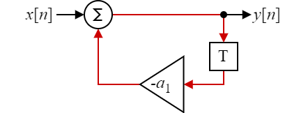 Fig 2: Simple, single tap IIR filter.
An application may demand that multiple samples (e.g. N=2) are processed per clock cycle.
All of the processing elements are doubled and the challenge at hand is managing the feedback path (memory elements).
The IIR tap can be unfolded as presented in Fig. 3.
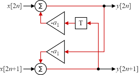 Fig 3: IIR filter unfolded to a 2-way parallel circuit which process 2 samples per clock cycle.
This however, comes at the cost of a much greater critical path. What was before a single multiplication and addition is now twice as much - without a single pipeline stage (!). This will seriously degrade the maximum achievable clock frequency of the circuit.
To improve the timing again the mathematical operations can be split and rearanged to match the circuit in Fig. 4.
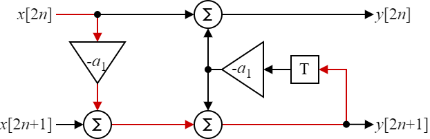 Fig 4: Unfolded IIR filter with expanded operations.
Here we still have a critical path that is longer than the original IIR filter. Futhermore there are now two additions in series (or a ternary addition) which may not map efficiently to a given FPGA architecture. It will still result in worse timing than the original circuit. Now however, some operations are in the forward path without recursive elements. Those can now be pipelined as depicted in Fig. 5.
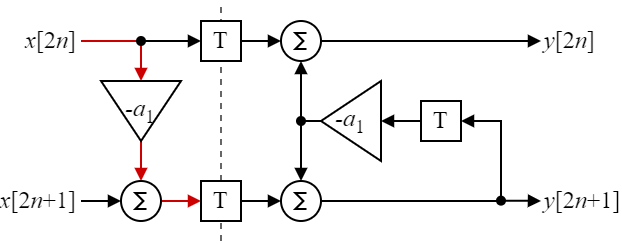 Fig 5: Final 2x unfolded, rearanged and pipelined IIR filter.
Theoretically, we now have the same critical path as the single IIR filter but now it will process twice the samples per clock cycle. This should be motivation enough to propose a general approach to unfolding recursive digital logic.
Sidenote: the true critital path may vary. The single IIR filter could be implemented in a single DSP48 instance. The second multiplier with two subsequent additions will not fit into a DSP48 slice and may require either an additional DSP48 slice or an adder chain in LUT fabric.
Circuit Unfolding Theory
In practice, algorithms consist of many more internal state signals (memory!). It is not practical to perform the above calculations by hand. There is a systematic way to perform unfolding on circuits.
- \(M\) Unfolding factor (i.e. oversampling factor)
- \(N_i\) parallel computational block \(i\) (where \(i={0,1,2...M-1}\))
Therefore, there are \(M\) blocks denoted \(N_i\). The input samples into block \(N_i\) are \(x[Mn+i]\) and the output samples of block \(N_i\) are \(y[Mn+i]\).
- \(L\) previous (non-unfolded) internal delay elements
- \(K\) unfolded delay elements
An internal state from block \(N_i\) with \(L\) delay elements is connected to block \(N_j\) with \(K\) delay elements. With the equations being:
\[j=(i+L)\,\mathrm{mod}\,M\] \[K = \left\lfloor{ \frac{i+L}{M} } \right\rfloor\]Applied Examples
2-tap IIR
Let us consider a 2-tap IIR filter in Fig. 6.
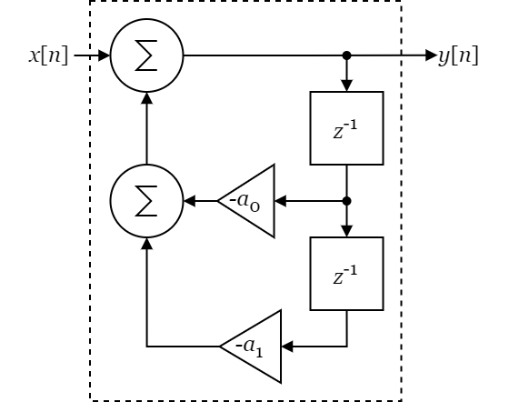 Fig 6: 2-tap IIR filter.
We are only interested in the memory elements in the feedback path. Therefore the 2-tap IIR filter can be abstracted
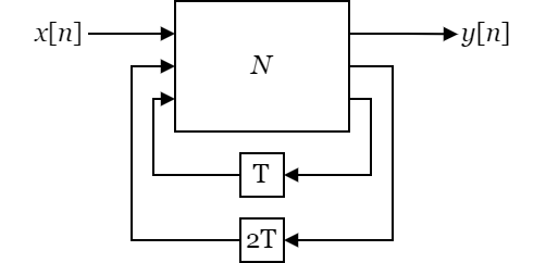 Fig 7: Abstract view of a 2-tap IIR filter.
The IIR filter shall be unfolded by a factor of 2.
It is therefore copied and each IIR instance shall process every other sample.
The instances are denoted N0 and N1.
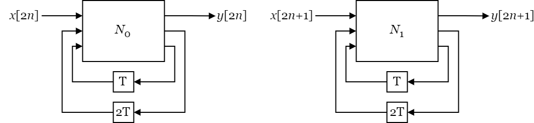 Fig 8: Abstract view of two 2-tap IIR filters.
Now the systematic equations can be applied and will result in the following table:
i |
L |
j |
K |
|---|---|---|---|
0 |
1 |
1 |
0 |
0 |
2 |
0 |
1 |
1 |
1 |
0 |
1 |
1 |
2 |
1 |
1 |
For example, the first row reads as follows:
“Connect the signal of block N0 which had 1 delay element to block N1 using 0 delay elements.”
If done for every signal, the resulting circuit will look like this:
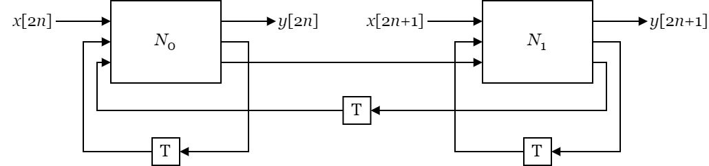 Fig 9: Fully unfolded 2-tap IIR filter.
5-tap IIR
Another example for good measure. Take a 5-tap IIR with more internal delay elements.
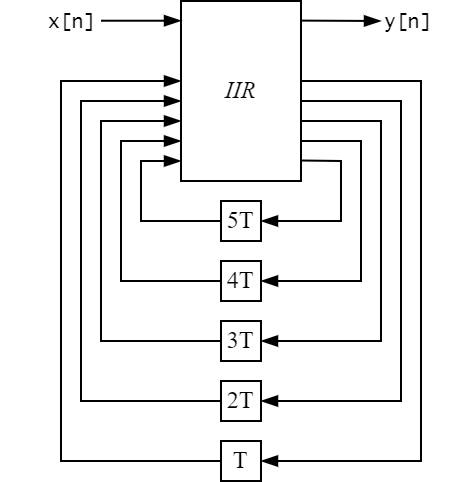 Fig 7: Abstract view of a 5-tap IIR filter.
i |
L |
j |
K |
|---|---|---|---|
0 |
5 |
1 |
2 |
0 |
4 |
0 |
2 |
0 |
3 |
1 |
1 |
0 |
2 |
0 |
1 |
0 |
1 |
1 |
0 |
1 |
5 |
0 |
3 |
1 |
4 |
1 |
2 |
1 |
3 |
0 |
2 |
1 |
2 |
1 |
1 |
1 |
1 |
0 |
1 |
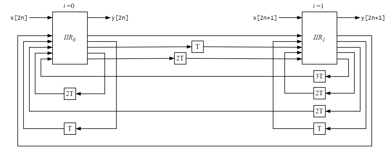 Fig 11: Fully unfolded 5-tap IIR filter.