 Fig 1: Schematics of the simulated crosspoint switch with individual enable signals for each
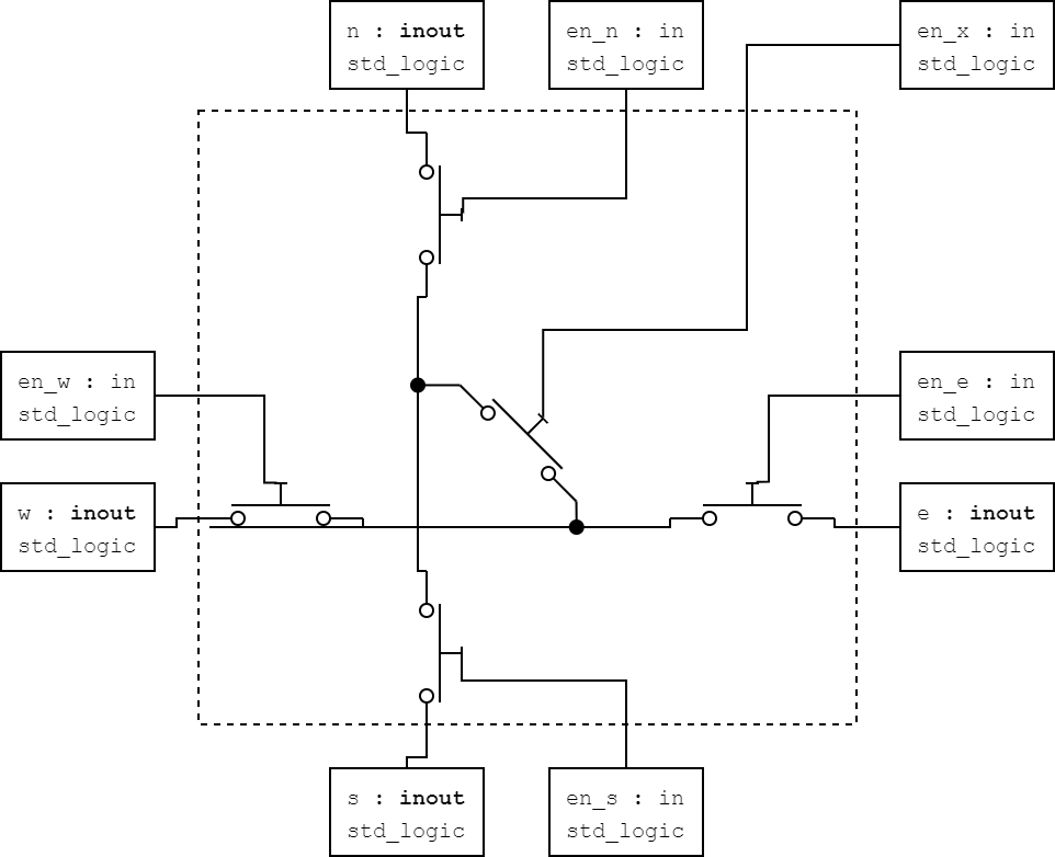
 inout port.
The whole ordeal of building my own FPGA is a great adventure and I am happy that you are tagging along for the whole journey. It is an adventure because I want to do it correctly. This is the first time for me to touch the topic of ASIC design. Any ASIC designer would now laugh at me because I am building an ASIC with a soldering iron. However, hear me out. Before ordering any circuit boards and chips, I want to make sure my conceptualized idea works in simulation. Therefore, I modelled all the 7400 logic ICs in my design in VHDL to then interconnect like they would be on the PCB. I can then test out various bitstreams and test the functionality ahead of hardware production.
To do so, not only do I need to model the digital chips but also the interconnect.
And the interconnect, flexible as it should be, consists of many inout ports. The routing will ultimately be decided by the bitstream.
I therefore cannot use GENERICs or GENERATE statements since the functionality of the port is decided at runtime.
Now, I grew up with VHDL, that is why I started modelling this project in VHDL.
VHDL however, is not designed to run gate level simulation of digital logic.
The component that would inevitably have to be a gate level interaction is the crosspoint switch in the interconnect of my FPGA architecture.
This switch comes with the most challenging functionality to model:
- It has several
inoutports which change their property to eitherinoroutdepending if anotherinoutsignal isZor0/1
VHDL does not like inout ports. We traditionally only use it on hardware features in an FPGA that are truly an inout port like a GPIO pad.
In Verilog you could simply use the tranif1 statement to achieve a MOSFET switch which has two inout ports and an en (enable) signal to connect both ports together.
When I struggled to achieve tranif1 characteristics in VHDL, I briefly tried to switch to Verilog. Only to find out, that Verilator does not support the tranif1 statement.
I would have to cheat my way around in either language. And that is why I stayed with VHDL and the open source GHDL compiler.
Some of my first attempts included statements like the following pseudocode, where a concurrent assignement checks if either port a or port b is actively driven:
if( (a=='1' or a=='0') and (en=='1')):
   b = a
if( (b=='1' or b=='0') and (en=='1')):
   a = b
Or in VHDL it will look like this:
1
2
3
4
5
6
7
8
9
10
11
12
13
14
15
16
17
18
19
20
21
library ieee;
use ieee.std_logic_1164.all;

entity digital_switch is
    port(
        en : in    std_logic;
        d1 : inout std_logic;
        d2 : inout std_logic
    );
end entity;

architecture arch of digital_switch is
begin

    d1 <= '1' when (d2 = '1' and en = '1') else
          '0' when (d2 = '0' and en = '1') else 'Z';

    d2 <= '1' when (d1 = '1' and en = '0') else
          '0' when (d1 = '0' and en = '0') else 'Z';

end architecture;
This switch worked in my simulations. But I would also need more complex switches in the switchbox (sw_box.vhd) entity.
This switch consists of 4 inout ports, 4 enable switches for each port and a common crosspoint switch to connect the north-south axis with the east-west axis.
Using the same method will run into delta-cycle problems because once either of the ports is driven by the internal concurrent assignment, it will trigger the other if-statement to infinity. The simulator cannot converge the result. This error only seems to occur with the more complex crosspoint switch and only when connecting it to other inout ports of the interconnect.
For the crosspoint switch I had to use a different approach.
The concurrent assignment would determine at startup, which of its inout ports is the active driving source.
After the active driver is determined, it will treat all other ports as followers to that source.
The disadvantage of this method is that it will not allow for bitstream reconfiguration once the simulation has started.
But this is a trade-off I can live with.
The code of this crosspoint can be found in newsw.vhd.